GY-521 Gyro + Accelerometer with Arduino

Why use a Gyroscope or Accelerometer?
In this blog post, I will explain what gyroscopes and accelerometers are and how they are used in mechatronics applications. Gyroscopes and accelerometers are types of inertial sensors that measure motion in different ways. They are often used together to provide more accurate and complete information about the orientation and movement of an object.
Gyroscopes measure the angular velocity or rotation rate of an object around one or more axes. They use the Coriolis effect, which is the apparent force that acts on a mass moving in a rotating frame of reference. By measuring the displacement of a vibrating mass due to the Coriolis force, gyroscopes can determine the angular velocity of the object. Gyroscopes are useful for measuring the attitude (pitch, roll, and yaw) of an object, such as a robot, a drone, or a vehicle.
Accelerometers measure the linear acceleration or force acting on an object along one or more axes. They use a mass-spring system, where a mass is attached to a spring and displaced by an external force. By measuring the displacement of the mass, accelerometers can determine the acceleration of the object. Accelerometers are useful for measuring the tilt or inclination of an object with respect to the gravity, as well as the vibration, shock, or motion of an object.
Gyrometers and accelerometers complement each other, as they can measure different aspects of motion. However, they also have some limitations and challenges. For example, gyrometers are prone to drift over time due to integration errors, while accelerometers are sensitive to noise and external forces other than gravity. Therefore, they are often combined with other sensors, such as magnetometers, which measure the magnetic field of the earth and provide a reference for the heading of the object.
One of the applications of gyroscopes and accelerometers in mechatronics is inertial navigation systems (INS), which use these sensors to estimate the position, velocity, and orientation of an object without relying on external references, such as GPS or landmarks. INS are widely used in aerospace, marine, and military applications, where GPS signals may be unavailable or unreliable. INS use a combination of gyroscopes, accelerometers, and sometimes magnetometers to measure the motion of an object and integrate it over time to obtain its current state.
Another application of gyrometers and accelerometers in mechatronics is gesture recognition, which uses these sensors to detect and interpret human gestures, such as hand movements or head rotations. Gesture recognition can be used for human-machine interaction, such as controlling a device with gestures or providing feedback to the user. Gesture recognition uses gyrometers and accelerometers to measure the orientation and motion of the human body part that performs the gesture and compare it with predefined patterns or models.
In conclusion, gyroscopes and accelerometers are important sensors for mechatronics applications that involve motion detection and analysis. They can measure different aspects of motion, such as rotation and acceleration, and provide information about the orientation and movement of an object. They can be used alone or in combination with other sensors to improve their accuracy and reliability. They can be applied to various domains, such as navigation, gesture recognition, robotics, gaming, health care, and sports.
GY-521 Example Usage with Arduino
The GY-521 breakdown board (HiLetgo 3pcs GY-521 MPU-6050 MPU6050 3 Axis Accelerometer Gyroscope Module 6 DOF 6-axis Accelerometer Gyroscope Sensor Module 16 Bit AD Converter Data Output IIC I2C for Arduino: Amazon.com: Industrial & Scientific) combines a gyroscope, 3-axis accelerometer, and temperature sensor into a single SCL/SDA interface.
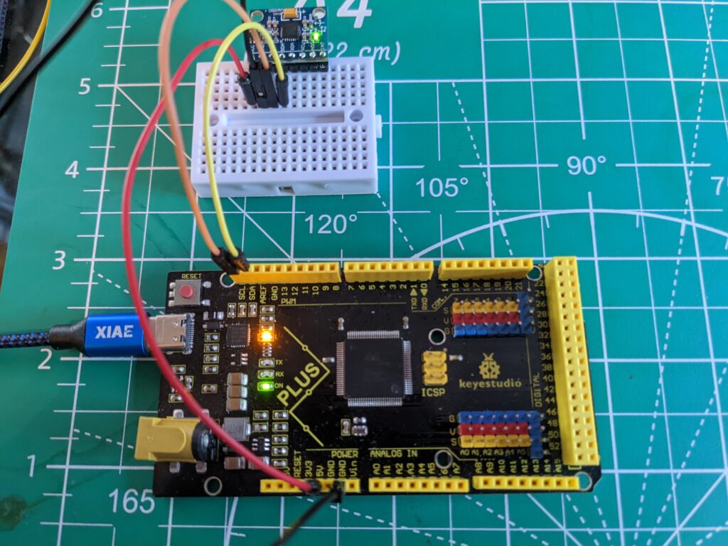
In this experiment we will connect to the GY-521 and read/verify sensor values while manipulating the board.
Materials
- GY-521 Breakout Board
- Arduino
- Jumpers (4)
- Breadboard
Steps
- Depending on the package and use case, you may need to solder the headings onto the breakout board.
- Connect VCC and GND to Arduino 5v and GND pin
- Connect the SCL and SDA pins to Arduino (the specific pin numbers will vary depending on the Arduino model)
- Load sample sketch onto Arduino board: blog/my521_example.ino at main · davidinwald/blog (github.com)
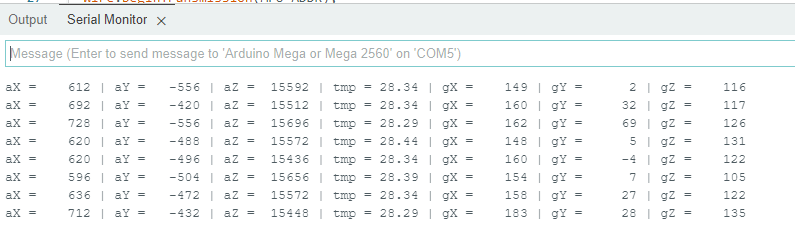
- Upload Sketch, and open the serial monitor to view the raw data printing with 500ms delay
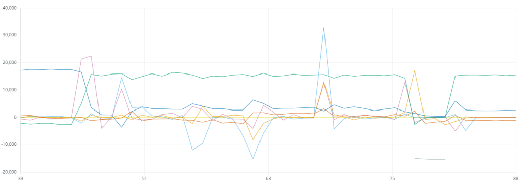
The serial plotter can be helpful to confirm/visualize:
Note: the board should have silkscreen that serves as reference for identifying x and y axes (bottom-right in this photo):
